EC900 User Manual
Edge Computer EC900 Series
User Manual
(Applicable for Debian10,IEOS V2.0.0 and above)
Version2.0, October 2023
The software described in this manual is provided according to the license agreement and can only be used according to the terms of the agreement.
Copyright Notice
© 2023 InHand Networks.All rights reserved.
Trademarks
The InHand logo is a registered trademark of InHand Networks.
All other trademarks or registered trademarks in this manual belong to their respective manufacturers.
Disclaimer
InHand Networks reserves the right to change this manual, and the product is subject to subsequent changes without prior notice. We will not be responsible for any direct, indirect, intentional, or unintentional damages and hidden dangers caused by improper installation and use.
1 Introduction
This user's manual is for the EC900 series of edge computers based on the Arm architecture and covers a complete set of instructions for all supported models. Before referring to these sections, verify that the hardware specifications of your computer model support the features/Settings covered.
2 Hardware installation instructions
In this chapter, we will cover the hardware installation instructions for the EC900 series of edge computers based on the Arm architecture.
2.1 Introduction
The following sections describe the application of external connectors and pin distribution of the EC942 series, using the EC942 series as an example.
2.2 EC942 panel
Top surface panel
Front
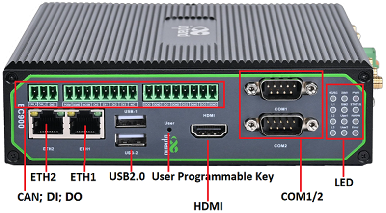 2.3 EC942 external connector
2.3.1 Ethernet
This is a dual RJ45 connector for Ethernet connection
The EC942 has 2 RJ45 Ethernet ports and supports 10M/100M/1000M adaptive rates.
Green light: LINK indicator, 1000M interface is on for the end device, and 10/100M interface is off for the end device.
Yellow light: ACT light, flashing when there is data
2.3.2 Serial port
EC942 supports two-channel serial port, support RS-232 or RS-485 or RS-422 communication, software can be configured.
2.3.3 CAN
EC942 has 1-way CAN bus interface and supports CAN 2.0A/B standard. It is compatible with CAN FD and can achieve a maximum rate of 5Mbps.
2.3.4 Switching Input interface (Digital Input)
2.3.5 Switching Output interface (Digital Output)
2.3.6 USB
The EC942 provides two USB 2.0 Host ports.
2.3.7 LED
EC942 has 12 LED lights to indicate the power supply and system operation status respectively.
Cellular signal strength indicator
In addition to the combination of L1, L2, L3 signal lights to indicate cellular signal strength, there is also a set of LED combinations to mark the process of restoring the factory.
After executing the restore factory Settings, the system will perform a restart, after the restart is completed, the restore factory is not completed, at this time WARN light and ERROR flashing, STATUS off, in this state can not power off the device, otherwise it may lead to the loss of some files and affect the system function. This state will last for 30 seconds, when the factory recovery is completed, WARN and ERROR will go off, and STATUS will flash.
2.3.8 User programmable keys
EC942 provides API interface, the user can call the API interface to detect the state of the programmable key, and then implement their own key logic.
2.3.9 DC input
The EC942 supports 12 to 48V DC input
2.3.10 SIM card slot
The EC942 supports 2 SIM card slots, the SIM card needs to be installed with power off, the SIM card is pressed into the slot.
2.3.11 MicroSD card slot
The EC942 has a slot for the MircoSD card, SD does not support hotplug and needs to be plugged in and out with power off. After inserting the SD card and powering up the device, the system will automatically mount all partitions.
2.3.12 Restore factory keys
There is a reset button for the system to restore the factory. Refer to Restore Factory Settings to do so.
2.3.13 Switch the machine button
EC942 is equipped with an on-off button for switching the machine on and off.
2.3.14 Antenna interface
There are 5 antenna interfaces in EC942, and the number of antennas standard with different models is different. The antenna is screwed into the corresponding antenna interface to complete the antenna installation.
2.3.15 Dial switch
The dial switch controls the pull up and pull down resistance of the 485 bus. The pull up and down resistance can be selected to increase the number of 485 bus loaded devices.
2.3.15 mSATA hard disk interface
EC942 supports mSata hard disk, and the factory does not come with mSata hard disk by default. If users have large capacity storage requirements, they need to buy mSata hard disk from themselves, or they can consult Inhantel for mSATA purchase.
3 Getting Started
In this chapter, we will cover the basic configuration of EC900, an edge computer based on Arm architecture.
3.1 Connect to the EC900
You will need a computer that you can use to connect to the EC900 and log in to the command-line interface. It can be connected by means of an Ethernet cable.
Factory default username and password:
Username: edge
Password: security@edge
EC900 devices are factory created root by default, but login is disabled. If you need to use the root user, change the system configuration manually and type sudo -s to switch to the root user. The user edge is in the sudo group, so you can use sudo under the edge user to execute system-level commands. See the sudo Mechanism section in Chapter 5 for additional details.
Tips
When command not found appears, type sudo -s to switch to the root user or use the sudo command to operate.
Note
For security reasons, we recommend that you disable the default user account and create your own.
3.1.1 Connecting via the SSH Console
The EC900 supports SSH connections over Ethernet. Connect to the EC900 using the following default IP address.
3.1.1.1 Linux users
Tips
These steps apply if you are connecting to EC900 on a Linux PC. Please do not apply these steps to the EC900 device itself. Before you run the ssh command, be sure to configure your PC's Ethernet port IP address to be within a specific range. ETH1:192.168.3.0/24, ETH2:192.168.4.0/24.
Use the ssh command to access the ETH1 port of the EC900 on a Linux PC.
Type yes to continue to complete the connection.
When the terminal prompt edge@edge-computer:~$appears and shell commands can be entered, the connection is successful.
3.1.1.2 Windows users
Tips
These steps apply if you are connecting the EC900 on a Windows PC. Please do not apply these steps to the EC900 device itself.
Make the following steps on your Windows PC
Click the link http://www.chiark.greenend.org.uk/~sgtatham/putty/download.html, download PuTTY (free) software, SSH command in Windows environment to establish a connection to the edge computer EC900. The following is an example of using SSH to connect:
3.2 User Account management
3.2.1 Switch to the root user
You can use the sudo -s command to switch to the root user. For security reasons, do not operate all commands as root.
Tips
Click on the link for more information on sudo commands.
Pay attention to
You may get a "permission denied" message when using some pipe or redirect behavior without root permissions. In this case, you must use 'sudo su -c' instead of '>','<','>>','<<','etc', etc. You need to include the full command in single quotes.
3.2.2 Creating and deleting user accounts
You can create and delete a user's account using the useradd and userdel commands. Be sure to use these commands in the home screen to set the relevant access rights for that account. Here is an example of how to create test1 in the sudo group (the default login environment for test1 users is bash and their home directory is /home/test1)
To change test1's password, use the passwd command, enter the new password and repeat to confirm the change
If you want to remove user test1, use the command userdel
3.2.3 Disable the default user account
Note
You should first create a user account before disabling the default account
Use the passwd command to lock the default user account so that edge users cannot log in
Unlock the edge user
3.3 Network administration and system administration
The EC942 is based on debian 10, so native Linux commands can be used for network management and system administration; In order to facilitate user configuration, InHand has developed a set of IEOS system programs, providing a web interface, users can easily through the web network management and system management, but it should be noted that when the IEOS function is enabled, IEOS will take over the network management and system management. At this time through the Linux native command for network management and system management may fail; IEOS is enabled by default, if users need to perform network management and system management based on Linux native command line, they need to close IEOS first.
3.3.1 web Management based on IEOS
IEOS is a set of network management and system management program running on Linux system developed by InHand. IEOS provides web interface, users can access Ethernet port ip address, cellular dial-up, Wi-Fi Station, DHCP Client/Server, static routing, and network management through the web. Firewalls and other network configuration; System time, time zone, firmware upgrade and system restart can also be operated; In addition, IEOS also supports docking with InHand device management platform DeviceLive. Users can remotely monitor and manage EC942 devices through DeviceLive platform.
IEOS adopts the design scheme of status and configuration separation, which is divided into three functional sections: network management, system management and status. The network management menu and the system management menu can only be used for network and system related configuration, and the status information needs to be unified to the status page.
Important note: When using IEOS program to manage network configuration and system configuration, if you use Linux native commands at the same time, the two may affect each other, resulting in abnormal running state. It is recommended that the configuration supported by IEOS be managed through IEOS web, and the configuration not supported by IEOS, such as VPN, can be combined with native Linux commands to achieve the configuration goal.
3.3.1.1 Login to the web
Considering that the user's program may need to use the standard HTTP/HTTPS port number 80/443, IEOS uses the port number 9100 as the HTTPS connection port, and does not support access through HTTP; When the user uses HTTP to access the web, it will automatically jump to HTTPS. This document uses eth2's default address of 192.168.4.100 as an example. The user enters 192.168.4.100:9100 in the browser and is taken to the login page
Important note: When IEOS programs are enabled, some port numbers will be reserved for internal communication. The reserved port numbers range from 9100 to 9200. After IEOS is enabled, client programs should avoid using these port numbers, or it may cause conflicts and malfunction.
3.3.1.2 Network management
3.3.1.2.1 Configuring the Ethernet interface
Configure the eth1 interface with a static IP address
Configure the eth1 interface with a DHCP Client
Start the dhcp server function on the eth1 interface and assign an address to the eth1 unhooked device
DHCP Server configuration parameters description:
Enable DHCP Server: The switch of DHCP Server function
Starting Address: Starting base address of DHCP Server address pool, network segment + starting address = starting ip address of address pool. In the screenshot, the network segment of eth1 is 192.168.3.0/24, and the base address is 1, then the starting address of the address pool is 192.168.3.1/24.
Max Address Number: The maximum number of addresses in the address pool.
Lease period: The length of the lease period
3.3.1.2.2 Configure cellular dialing
Cellular network parameters Description:
Enabled: The switch of cellular function; Enabled by default.
10. Profiles: A set of dial parameters used to configure APN, username, password, and authentication methods when dialing a dedicated network card. If you are not a dedicated network card, you usually do not need to change the configuration here. You can add up to 10 records to the dial-up parameter set.
Network Mode: The network mode of the cell, you can choose 3G, 4G and other related network mode, such as LTE, WCDMA, etc. If it is not clear which network mode to choose, select automatic; The program will automatically select the most appropriate network mode. The default is automatic.
Enable Default Route: Enable the function of adding default route. When enabled, a default route of cellular port will be added when the dial is successful. The default route is enabled.
Metric: This is the metric for the default routing of the cellular port. When default routing is configured on the cellular, Wi-Fi, and Ethernet ports, the metric with the lowest value is used.
Dual SIM Enabled: Dual Sim enabled. In order to improve the reliability of the network, EC942 supports dual SIM and single dial. Two sim cards need to be inserted into the device. If the sim1 card fails to dial because of unpaid charges, it will automatically switch to the sim2 card for dialing. By default, it is off.
Main SIM: The main sim card, when dialing, the selected sim card will be preferred for dialing. When dialing fails to reach a certain number of times, when switching to another sim card for dialing, the default is to use sim1 for dialing.
Max Number of Dials: When the dual-SIM single-dial function is enabled, the current sim card will be dialed to another sim card for dialing when the number of dials reaches a specified number.
APN Profile: sim card selected dialing parameters set, the default value is automatic. Usually special network card usually need to configure the dial parameter set, and select the Index of the dial parameter set here.
PIN Code: The PIN code of the sim card.
Wireless cellular networks are complex, sometimes there will be dial-up false connection, that is, the dial-up state is successful, but the target address can not be ping; When this happens, you can simply dial again and get back to normal. IEOS cellular dialing supports ICMP probing to detect spurious connections. It is recommended that customers with cellular connections enable ICMP probing so that false connections can be quickly recovered.
ICMP probe parameters:
ICMP Detection Server Probes: ICMP probe address; 2 probe addresses can be configured, as long as 1 address is successfully probed, it means that there is no fake connection in the cell. When neither address is configured, ICMP probing is turned off.
Detection Interval: How often should ICMP probes be performed?
Detection Timeout: The duration of ICMP probe timeout. If no probe response packet is received, the probe is considered to have failed
Detection Max Retries: the maximum number of probes; When a probe fails to reach this value, a redial is triggered. Range [1,5]
Detection Strict: Whether strict detection is enabled. When strict detection is turned off, the detection program will detect whether the packet received by the cellular interface has changed in each detection cycle. If there is a change, it means that the cellular network is working, and ICMP packets will not be sent for detection, so as to save some traffic; If the probe is turned on, ICMP probe packets will be sent periodically regardless of whether the number of packets received by the cellular interface has changed. By default, it is off.
In Advanced configuration are some less commonly used Settings options.
Debug Mode enabled: Whether the debug function is enabled. After enabled, some dial-related debugging information will be added to the log, and it is disabled by default.
Enable Redial: This enables unlimited redial. In some cases, dialing will be in an abnormal state, which can be restored by rebooting the system; By default infinite redialing is turned off, and the system will be restarted to try to recover after a certain number of dialing failures. Since dialing is enabled by default, some customers without sim card, dialing failure, the system will restart, in this case, you can open unlimited redialing; In this way, no matter how many times the dialing fails, the system will not restart.
Dial Interval; But if a dial fails, the amount of time to wait before making another dial.
Signal Query Interval: Signal query interval. When the signal is bad, you may have problems with false connections; At this time, redialing has a certain probability to solve the problem of false connection. The dialing program will check the signal strength at regular intervals; here, the signal detection period is configured.
3.3.1.2.3 Configure the Wi-Fi Station
Enable Wi-Fi: Enable the switch; Off by default
Client SSID: The ssid you want to connect to, you can enter it manually; You can also use the scan button to get nearby SSIDs that you can connect to
Enable Default Route: Enable the function of adding default route. If enabled, when the wifi connection is successful, a default route of wlan port will be added. The default route is enabled.
Metric: This is the metric for the default route of the wifi port. When the default route is configured for the cellular, Wi-Fi, and Ethernet ports, the metric with the lowest value is applied.
Auth Method: Auth method, supports no auth, WPA-PSK, WPA2-PSK, WPA-PSK/WPA2-PSK Mixed
Encrypt Mode: encrypt mode; CCMP, TKIP, TKIP and CCMP are supported
WPA/WPA2 PSK Key: Key information
3.3.1.2.4 Configuring static routes
This is a static routing for Ethernet. When the default routing for Ethernet, cellular, and wifi is configured, the default route with the lowest metric value will take effect. You need to make sure that the Metric value of the default route is different.
Static route configuration parameters:
Interface: The outgoing interface of the static route
Target: The target network
Netmask: The target network mask
Gateway: Next hop address
Metric: The metric for the static route
3.3.1.2.5 Configuring the firewall
Only the iptables command is currently supported for configuration.
3.3.1.2.6 Configuring DNS
DNS Servers: DNS Server address, up to 4 can be configured
Domain name hijacking: Domain name hijacking function, can realize the binding between IP address and domain name.
3.3.1.2.7 Network diagnostics
Network diagnostics support ping, traceroute and nslookup functions.
3.3.1.3 System administration
3.3.1.3.1 Basic configuration
Cloud management
Enabled: the enable switch that connects to the DeviceLive platform; DeviceLive is the remote monitoring and management platform of InHand equipment;
Cloud Server: DeviceLive platform has 2 addresses; One is the address of the domestic platform, the other is the address of the overseas platform; Here you choose which platform to connect to.
Time zone and NTP client
Up to 10 NTP Server addresses can be configured, and the program periodically sends synchronization requests to each server address in turn. After the synchronization is successful, the system time is written to the RTC and no longer continues to send synchronization requests to the later NTP servers.
In addition to using NTP to synchronize the time, there is a synchronization button in the Device Info status page to synchronize the time manually, but only when the device time and the local time (the time of accessing the computer used by the device) differ by more than 3s, this synchronization button will be displayed.
Configuration import, export and factory restore are supported here.
3.3.1.3.2 Firmware upgrade
The automatic restart option is turned off by default. After upgrading the firmware, you need to manually restart the system to take effect; When the automatic restart option is enabled, the system will be restarted automatically after the firmware upgrade is successful.
3.3.1.3.3 Others
This page has 2 functions: restart the system and reset the system. Resetting the system needs to be used carefully. The resetting system function will restore the system configuration status and file system status to the factory, which means that the software installed by the user will also be cleared.
3.3.1.4 Status
3.3.1.4.1 Equipment information
The device information status page shows the hostname, device model, serial number, firmware version, kernel version, file system version and an overview of CPU, memory and disk space usage.
3.3.1.4.2 Cellular dialing status information
The cellular dialing status page shows the sim card, IMEI, IMSI, ICCID, signal strength used by the current dialing, as well as the IP address, DNS and other information obtained by the dialing.
3.3.1.4.3 Wi-Fi Station status information
The Wi-Fi status page shows the IP address, gateway, and DNS information obtained after the Wi-Fi connection was successful.
3.3.1.4.4 DHCP Server status information
The DHCP Server status page shows the assigned IP address of the device as a DHCP Server, the client hostname, the client host mac, and the expiration time.
3.3.1.4.5 Route state information
The route status page displays IPv4 direct route, static route and route neighbor information.
3.3.1.4.6 Firewall status information
Firewall status information shows filtering rules, IP address mapping rules and other information.
3.3.1.4.7 Log information
The log page can view the system log, user log and set the log level, including Error, Info, Debug and other levels. Logs can also be downloaded locally.
3.3.2 Linux-based command-line management
When using the Linux command line for network and system configuration, the first thing you need to do is close the IEOS program. IEOS is managed through systemctl,
Shutting down IEOS is done as follows:
systemctl stop ieos_daemon
This shutdown only applies to this startup, and IEOS programs will still start after the system is rebooted. Here's how to prevent IEOS programs from starting:
systemctl disable ieos_daemon
Important note: After IEOS is closed, wireless networking functions such as dialing and Wi-Fi need to be implemented based on native Linux commands, and it is not possible to interface with the DeviceLive platform to remotely manage devices.
3.3.2.1 Network management
3.3.2.1.1 Set up a static IP address
If you want to set static IP address for EC942, through the command vim/etc/network/interfaces. D/eth1 or vim/etc/network/interfaces. D/for eth2 modify the corresponding network configuration file to the default gateway for Ethernet interface, address, Network and subnet mask. As an example, let's set a static IP address for the eth2 port:
After changing the interface IP configuration, run /etc/init.d/networking restart to restart the network service for the configuration to take effect.
3.3.2.1.2 Set up a dynamic IP address
If you want to for EC942 dynamic IP address, through the command vim/etc/network/interfaces. D/eth1 or vim/etc/network/interfaces. D/for eth2 modify the corresponding network configuration file, Setting it to DHCP after inet will automatically get the IP address.
Let's take an example of setting a dynamic IP for the eth1 port.
After changing the interface IP configuration, run /etc/init.d/networking restart to restart the network service for the configuration to take effect.
3.3.2.3 System administration
3.3.2.3.1 Querying the firmware version
To check the computer firmware version for EC942, type:
Add the -a option to see the full version information:
3.3.2.3.2 Viewing available disk space
To determine the amount of available drive space, use the df command with the -h option. The system will return the amount of drive space broken down by file system. For EC942 products, the disk partition available to the user is /dev/mmcblk0p8. Here's an example:
3.3.2.3.3 Querying product model information
The devinfo tool can view the product model information
3.3.2.3.4 Adjust the time
EC942 has two time Settings. One is system time and the other is RTC (Real Time Clock) time, which is maintained by the hardware of the EC942. Use the date command to query the current system time or to set a new system time. Use the hwclock command to query the current RTC time or set a new RTC time.
Use the command date MMDDhhmmYYYY to set the system time:
MM: month
DD: day
hh: hour
mm: a minute
YYYY: Year
RTC time can be set to system time using the following command
Click on the link below for more details about the date and time:
https://www.debian.org/doc/manuals/system-administrator/ch-sysadmin-time.html
https://wiki.debian.org/DateTime
3.3.2.3.5 set time zone
There are two ways to configure the time zone for EC942. One is to use the command tzselect. The other is to use the /etc/localtime file.
3.3.2.3.6 Use the tzselect command
When you type the tzselect command, you will be taken to the area selection screen. Select the approximate area (divided by continent and ocean) and enter the number in front of the continent or ocean
Then select the continent or the country under the ocean
Follow the steps above to get the China time zone keyword Asia/Shanghai and execute the following command to set the time zone
3.3.2.3.7 Using localtime files
The localtime zone is stored in /etc/localtime and is used by the GNU library for C (glibc) if no value is set for the TZ environment variable. This file is either a copy of /usr/share/zoneinfo/file or a symbolic link to it. If EC942 cannot find/usr/share/zoneinfo/file, please download from the web site you need the time zone information file (https://www.iana.org/time-zones), and links to the local time in the EC900 file.
Note
After successfully downloading the required time zone information file, unzip it, and then compile and generate the corresponding binary file using zic command. The generated time zone file is "/usr/share/zoneinfo/custom time zone filename".
Advanced configuration of peripheral interfaces
In this chapter, we will introduce the advanced configuration of peripheral interfaces for EC900, an edge computer based on Arm architecture.
4.1 Serial Port
EC942 has 2 serial ports, each of which supports RS-232, RS-422 and RS-485 multiple serial port modes. The default serial port mode is RS-232, and the serial port mode can be switched by using ih_uart_ctl command.
The device node corresponding to COM1 is /dev/ttyS3
The device node for COM2 is /dev/ttyS4
4.1.1 Change the serial port Settings
View and set the serial port with the stty command
To see the details, type sudo stty --help:
4.1.2 View serial port information:
4.1.3 Set the baud rate of COM1 serial port:
4.1.4 Set the baud rate of COM2 serial port
Note
Details about the stty command are available at the following link
http://www.gnu.org/software/coreutils/manual/coreutils.html
4.2 the USB interface
EC942 provides two USB 2.0 Host interfaces, which are mainly used to expand storage devices and connect to mice and keyboards
4.2.1 USB auto-mount
EC942 supports USB storage device hotplugging. It will mount all partitions automatically. EC942 will mount all USB storage device partitions to the /mnt/ path with the mount folder named usb_<node>_<num>. Where <node> is the device node name of the partition, and <num> can be a number from 0 to 9.
Note
Remember to enter the sync sync command before disconnecting your USB mass storage device to prevent data loss. When you disconnect your storage device, exit from the /media/* directory. If you stay in /media/usb*, the automatic uninstall process will fail. If this happens, type umount /media/usb* to manually unmount the device
4.2.2 micro SD card mounts automatically
EC942 supports micro SD memory card but does not support hotplugging. It will mount all partitions automatically. EC942 will mount all micro SD memory card partitions to the /mnt/ path with the mount folder named sd_<node>_<num>. Where <node> is the device node name of the partition, and <num> is a number from 0 to 9.
4.2.3 mSATA hard disk mounts automatically
(1) Log in to the system, run sudo fdisk -l, find your hard disk partition, as shown below is /dev/sda1
Format the partition to the desired filesystem, such as ext4
Create a mount point such as /mnt/sda1
(4) Edit vi /etc/fstab file,
Add /dev/sda1/mn/sda1 ext4 defaults,nofail,x-systemd.device-timeout=1s 0 0 to the end line, as shown below:
/dev/sda1: device partition, which needs to be configured by the user according to the actual situation
/mnt/sda1: mount point, which needs to be configured according to the actual situation
etx4 hard disk partition file system format, users need to configure according to the actual situation
defaults,nofail,x-systemd.device-timeout=1s 0 0 Fixed configuration, which is recommended, but can be modified as needed.
4.3 CAN bus interface
The CAN port of the EC942 supports the CAN bus.
4.3.1 Configure the connection CAN interface
By default, the CAN port will be initialized. If you need any other configuration, check the CAN device using the ip link command. To check the status of the CAN device, use the ip link command:
To configure the CAN device, use ip link set can0 down to turn the device off first
Then configure the bit rate (here's a 50k bit rate example) :
Finally turn the device back on
4.4 IO Debugging
The EC942 supports 4-way DI and 4-way DO. When you want to use IO port, please type dio_mgmt command to control io input and output. Usage of dio_mgmt:
dio_mgmt set D<I/O><number><HIGH/LOW> When you need to set a bit of IO port to high or low, type dio_mgmt set d <I/O><number>< high/low >
Print the corresponding IO level information by typing dio_mgmt show D<I/O><number>.
4.5 GPS
Some models of EC900 are integrated with GPS module, and the data serial port node is /dev/ttyS9.
If you want to view the details of the GPS, there are two ways to view it:
- Use stty to set up the serial port node and type cat to output the source data directly
- Typing gnss commands directly outputs the parsed time, latitude and longitude, and other information
4.6 Toggle the machine button
4.6.1 Turn off the device
1. Turn off the device by long pressing the on/off button for 8 seconds
2. You can use Linux commands to shut down all software running on the device and stop the system. However, after running this command, major components such as CPU, RAM, and storage devices will lose power.
4.6.2 Boot the device
Press the on/off button, and the system will perform the boot operation.
5 Safety
In this chapter, we will introduce the security mechanism of EC900, an edge computer based on ARM architecture.
5.1 sudo mechanism
In EC900, the root user is banned for better security. Sudo is a program that lets the system administrator allow an approved user to execute some commands as the root user or another user. The most basic rule is to give as few privileges as possible to get the job done. Using sudo is more secure than root session opening for a number of reasons, including:
• Grant privileges to normal users without having to know the root password (sudo will prompt for the current user's password)
• It's easy to run privileged commands via sudo, and the rest of the time, work as an unprivileged user, reducing potential damage due to wrong operations.
• Some system-level commands are not available directly to the user, as shown in the following example output:
5.2 Firewalls
Netfileter/iptables is an excellent and free firewall tool based on packet filtering which comes with nuix/linux system. It is very powerful and flexible, and can control the data packets flowing in, out and through the server in fine detail.
5.3 TPM2.0
TPM stands for "Trusted Platform Module" and it is a hardware security module designed to provide security and encryption capabilities for computer systems. It is a secure microcontroller that can be embedded in a computer system or sold as a standalone hardware device. It contains a cryptographic coprocessor for storing encryption keys, digital certificates, and other secure data, as well as supporting multiple cryptographic algorithms and security protocols. On EC942, the standard TPM2.0 protocol stack and TPM2.0 tools have been integrated for user use.
6 The system restores factory Settings and updates
In this chapter, we will describe how EC900, an edge computer based on Arm architecture, restores factory Settings and updates.
6.1 Restore factory Settings
There are two ways to restore factory Settings:
- By typing the command, the system will automatically restart and restore the factory Settings.
- Restore factory Settings by pressing:
- Long press the restore factory Settings button for 10-20s and see the warn light long on.
- When the warn light has turned on, release the Restore Factory Settings button.
- After releasing the Restore Factory Settings button, the error light blinks several times before the system starts to restart and perform Restore Factory Settings
- After the system restarts, the warn light and error light will flash, and status will be off; After about 30s, when both warn light and error light stop flashing and status starts flashing at the same time, the system is finished restoring the factory Settings.
6.2 System Upgrades
Get a USB key (micro SD card). If the USB key (SD card) has multiple partitions, use the first partition. It is recommended not to make multiple partitions. Usb key (SD card) partitions need to be formatted in FAT32 format. This document takes upgrading EC942-V2.0.0.img as an example to explain.
- Create an empty ec900_img directory in the root directory of the U disk (SD card), and put the EC942-V2.0.0.img file and md5.txt file published by inhand into the ec900_img directory.
- Make sure that the MD5.txt file only has the md5 hash value of EC942-V2.0.0.img line. EC942 does not support ota upgrade of multiple img images.
- Exit the USB flash drive (SD card) normally on the computer. Be careful not to unplug the USB key directly, but to select the "Exit" or "eject" action from the desktop.
- Insert the USB key (SD card) into the target EC900 device. The target device will automatically verify the EC942-V2.0.0.img file and perform OTA upgrade. The WARN and ERROR lights will be displayed accordingly during the upgrade. When WARN and ERROR return to normal, the upgrade operation is complete. Because the img file is large, it will take a long time to upgrade. Please wait patiently.
- After the upgrade, EC900 will write the key information in the upgrade to the log file in the ec900_img directory. Please check the related files.
7 Programming Guidelines
EC900 provides a device information description file in JSON format. Customers who need to operate IO, LED, serial port and other peripherals can obtain the device node information of these peripherals by querying the device description information file.
Device description file path: /tmp/ieos/etc/system_info.json, the content is as follows:
{
"device_info":{
"model_info":{
"model":"EC942
", "pn":"LQA8-W-G",
"sn":"CL9422343000019",
"oem":"inhand",
"features":"; std; cell-LQA8; wlan; io; tmp2;"
},
"software_info":{
"boot_loader":"1.0.1", "kernel
":"4.19.232",
"version":"V2.0.1-test.2",
"OS":"Debian GNU/Linux 10 (buster)"
},
"hardware_info":{
"arch":"arm64",
"soc":"rk3568",
"interface":{
"eth":[
{
"iface_name":"eth2",
"iface_mac":"2E:62:32:7B:B5:28"
}, {
"iface_name":"eth1", "iface_mac":"2A:62:32:7B:B5:28"
}
],
"wlan":[
{
"iface_name":"wlan0",
"iface_mac":"88:12:AC:FA:AD:53"
},
{
"iface_name":"wlan1", "iface_mac":"8A:12:AC:FA:AD:53"
}
]
}, "gpio":[
{
"gpio_name":"cellular_power",
"dev_node":"/sys/class/gpio/gpio0"
},
{
"gpio_name":"sim_switch",
"dev_node":"/sys/class/gpio/gpio19"
},
{
"gpio_name":"msata_power",
"dev_node":"/sys/class/gpio/gpio20"
},
{ "gpio_name":"gnss_power",
"dev_node":"/sys/class/gpio/gpio110" },
{ "gpio_name":"ble_power",
"dev_node":"/sys/class/gpio/gpio220" } ],
"user_key":[ { "user_key_name":"USER",
"dev_node":"/sys/class/gpio/gpio95" } ],
"uart":[ { "uart_name":"COM1",
"dev_node":"/dev/ttyS3" }, { "uart_name":"COM2",
"dev_node":"/dev/ttyS4" } ],
"io":{ "di":[ { "di
_na
me":"DI1",
"dev_node":"/sys/class/gpio/gpio487" },
{ "di_name":"
DI2",
"dev_node":"/sys/class/gpio/gpio488" },
{ "di_name":"DI3",
"dev_node":"/sys/class/gpio/gpio489" },
{ "di_name":"DI4",
"dev_node":"/sys/class/gpio/gpio490" } ],
"do":[ { "di_n
ame":"DO1",
"dev_node":"/sys/class/gpio/gpio491" },
{
"di_name":"DO2
", "dev_node":"/sys/class/gpio/gpio492" },
{ "di
_name":"DO3",
"dev_node":"/sys/class/gpio/gpio493" },
{ "di_name":"DO4",
"dev_node":"/sys/class/gpio/gpio494" } ] },
"led":[
{
"led_name"
:"USER1", "dev_node":"/sys/class/leds/user1" },
{ "led_name"
:"USER2",
"dev_node":"/sys/class/leds/user2" },
{ "
l
ed_name":"4G/5G", "dev_node":"/sys/class/leds/cell" },
{ "l
ed_name":"SIM1", "dev_node":"/sys/class/leds/sim1" },
{
"le
d_name":"SIM2", "dev_node":"/sys/class/leds/sim2" },
{ "
led_name":"WARN",
"dev_node":"/sys/class/leds/warn" },
{ "l
ed_name":"
ERROR", "dev_node":"/sys/class/leds/error" },
{ "led_nam
e":"STATUS",
"dev_node":"/sys/class/leds/status" },
{ "led_
nam
e":"L1", "dev_node":"/sys/class/leds/level1" },
{ "led_na
me":"L2",dev_node":"/sys/class/leds/level2"
},
{
"led_name":"L3",
"dev_node":"/sys/class/leds/level3"
}
]
}
}
}
A guide to IO Programming
Currently, there are a total of 8 IO interfaces on the device: for example, there are 4 input pins from DI0 to DI3 on the device panel; Do0-do3 are 4 output pins.
The IO device nodes can be obtained from the device description file /tmp/ieos/etc/system_info.json as follows:
DI0~DI3-----sys/class/gpio/gpio487~sys/class/gpio/gpio490
DO0~DO3------sys/class/gpio/gpio491~sys/class/gpio/gpio494
When you need to programming IO interface, direct manipulation background device nodes below the value value (sys/class/gpio/gpioxxx/value)
Case study:
When DO0 need to output high electricity at ordinary times, can be directly to sys/class/write 1 gpio/gpio491 / value
echo 1 > /sys/class/gpio/gpio491/value
When you need to check the DI0 level is, the same can be directly to check the sys/class/gpio gpio487 / the value of the value
cat /sys/class/gpio/gpio487/value
The full shell script:
7.2 Led Programming Guide
On the device, the user can use the two lights USER1 and USER2 to indicate the status. Please check the lamp label to confirm the position of the two lights USER1 and USER2.
According to the device description file /tmp/ieos/etc/system_info.json, the device nodes of USER1 and USER2 can be obtained as:
user1: /sys/class/leds/user1
user2: /sys/class/leds/user2
There are some control files in /sys/class/leds/user1 to control the attributes and status of leds:
/ sys/class/leds/user1 / brightness: this file is used to control the user1 lights on or off. Write 1 to always on, write 0 to always off.
/ sys/class/leds/user1 / trigger: leds trigger, can write the timer timer trigger, write none said cancel the trigger.
/ sys/class/leds/user1 / delay_on: it is time to file said led lights, is an unit with ms.
/ sys/class/leds/user1 / delay_off: it is time to file said led lights, is an unit with ms.
If trigger is configured for timing, the value in the brightness will no longer take effect and will automatically change to 0.
To control the brightness of user2, replace user1 with USER2 in the file path.
Example:
Write 1 to the brightness file when you need the USER1 light to be on
echo 1 > /sys/class/leds/user1/brightness
When the USER1 light is needed to flash, write the timer to the trigger file and control the time of light and off by delay_on and delay_off
Echo # start timer timer > / sys/class/leds light
echo 1 seconds/user1 / trigger
# > 1000 / sys/class/leds/user1 / delay_on echo out
# 1 seconds
1000 > /sys/class/leds/user1/delay_off
Full shell script:
7.3 Cross-compilation
A user's own c/ C ++ program can be cross-compiled by using the cross-compilation toolchain on the development machine, and then the object file is uploaded to the EC942 device for execution.
Cross-compiler package: gcc-linaro-6.3.1-2017.05-x86_64_aarch64-linux-gnu.tar.gz
Here's how to configure the environment variables for the cross-compilation toolchain:
- Unzip gcc-linaro-6.3.1-2017.05-x86_64_aarch64-linux-gnu.tar.gz to /opt on your development machine (you can also unzip it to any other PATH, adjust the path environment variable in step 2)
- Edit the ~/.bashrc file and add a line PATH=$PATH:/opt/gcc-linaro-6.3.1-2017.05-x86_64_aarch64-linux-gnu/bin at the end of the file
- Execute source ~/.bashrc to make the environment variables work in the current terminal; The newly opened terminal will take effect automatically.
Using the classic hello world program as an example, create the following directories and files
mkdir ~/example
touch ~/example/hello.c
touch ~/example/Makefile
The contents of the ~/example/hello.c file are as follows:
#include <stdio.h>
int main(void)
{
printf("hello, world! \n");
return 0;
}
The contents of the ~/example/Makefile are as follows:
# Define TARGET and source filenames
target := hellworld
DIRS := $(shell find.-maxdepth 3-type d)
SRCS := $(foreach dir,$(DIRS),$(wildcard $(dir)/*.c))
OBJS := $(SRCS:.c=.o)
CC=aarch64-linux-gnu-gcc
# Define compiler and compile options
CFLAGS := -Wall-Wextra -g-wno-unused-parameters
# define default TARGET
all: $(TARGET)
# define target file dependencies and compile commands
$(TARGET): $(OBJS)
$(CC) $(CFLAGS) $(LIBS) $^ -o $@
# Define the command to compile the source file to the target file
%.o: %.c
$(CC) $(CFLAGS) $(LIBS) -C $< -o $@
# Define command to clear temporary files
clean:
rm -f $(TARGET) $(OBJS)
# declare pseudo target ".PHONY"
.PHONY: all clean
Run make in the ~/example directory to generate the object file helloworld
Related Articles
EC300 User Manual
Edge Computer EC300 Series User Manual (Applicable for IEOS V2.0.0 and above) Version1.1, February 2024 www.inhandnetworks.com The software described in this manual is provided according to the license agreement and can only be used according to the ...InGateway902 User Manual
1. Product Introduction 1.1 Overview The InGateway902 (IG902 for short) series is a new-generation series of 4G edge computing gateways developed by InHand Networks for the Industrial IoT sector. It provides omnipresent, uninterrupted Internet access ...DeviceSupervisor Agent User's Manual
DeviceSupervisor Agent User's Manual (Applicable for IG & EC) Version3.0,April 2024 www.inhandnetworks.com.cn The software described in this manual is according to the license agreement, can only be used in accordance with the terms of the agreement. ...InSwitch Series Web Configuration Manual V1.0
Chapter 1 Basic Configuration 1.1 HTTP protocol configuration Switches support not only can be configured by CLI and SNMP protocol, it also supports being configured by web. HTTP service port configuration and time configuration of abnormal message ...InGateway502 Quick Start Manual
InGateway502 (IG502 for short) can provide rich networking functions and analysis of various mainstream industrial protocols such as ModbusTCP/RTU, and can be connected to mainstream loT cloud platforms such as AWS and Azure. Help customers quickly ...